Here is a story of one cheap HDMI digitizing device. I have wanted to connect devices with HDMI output Open Broadcast Studio video mixer/streaming software running on PC. Usually HDMI to USB adapters are expensive boxes (around $100 or more). But the I saw this really cheap (€16,15 / US$ 18.99) Mini Portable HD USB 2.0 Port HD 1080P 60fps Monitor Video Capture Card For PC device that looked like worth a try.
The specifications looked promising for the price:


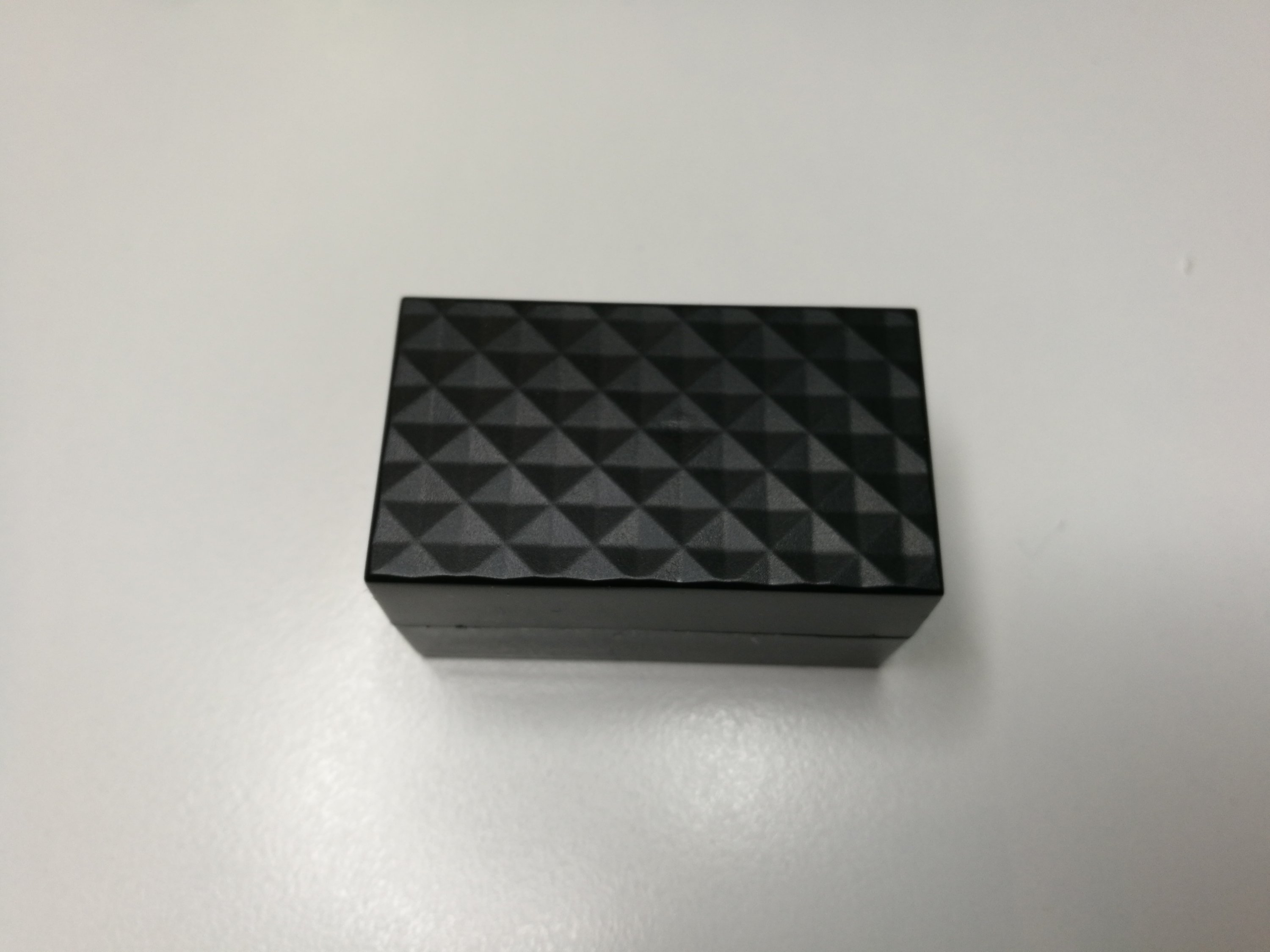
I received it like this. Driver CD broken. It did not work without it – as plugging it to Windows 10 PC detected it as some video device, but trying to really use it led to blue screen of death crash. ![]() So it was not clearly plug&play.
So it was not clearly plug&play.
The seller company gave money back and they did not want the trash back.
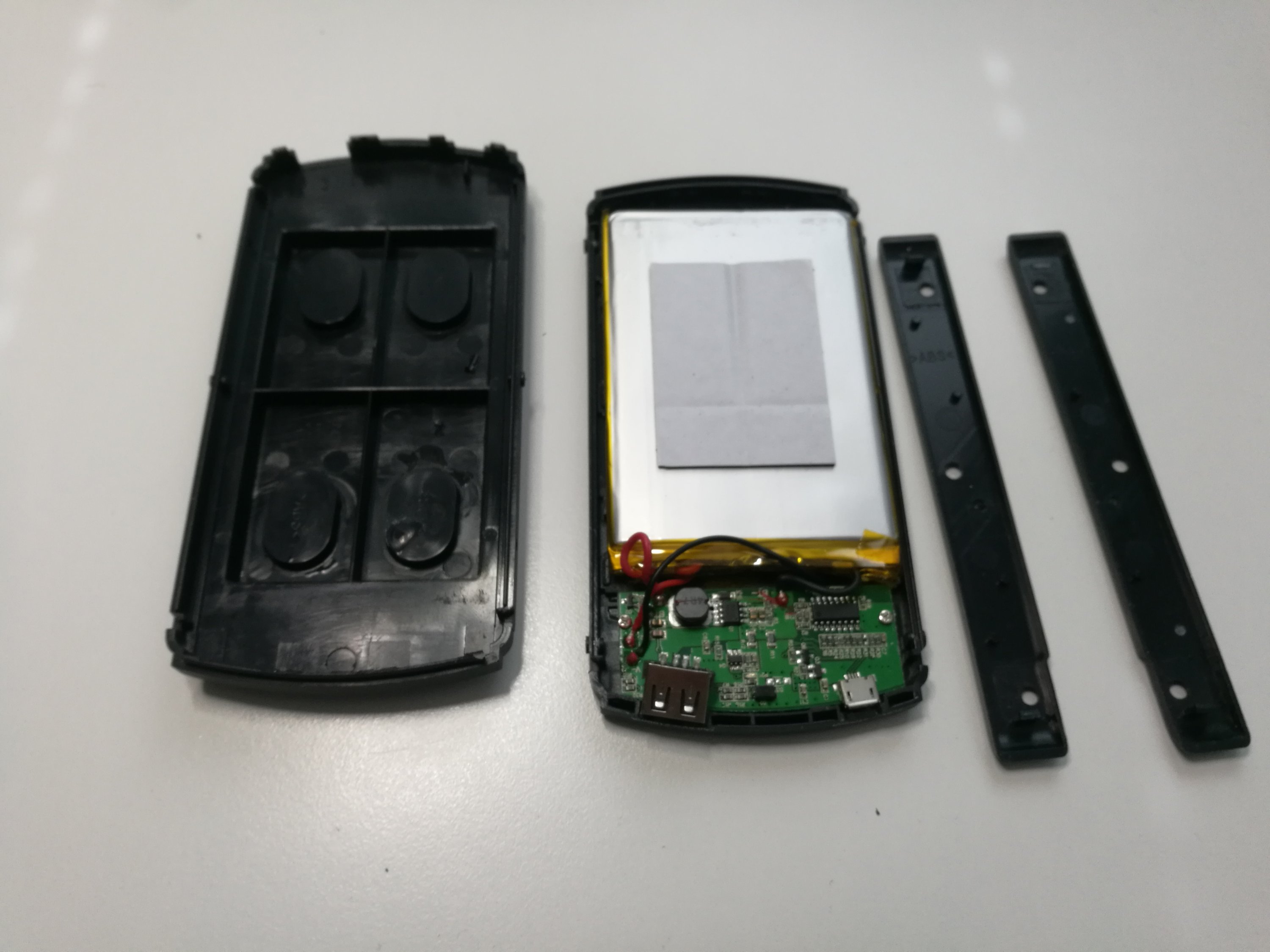
So I decided to take a look inside because I was curious what is inside this device.

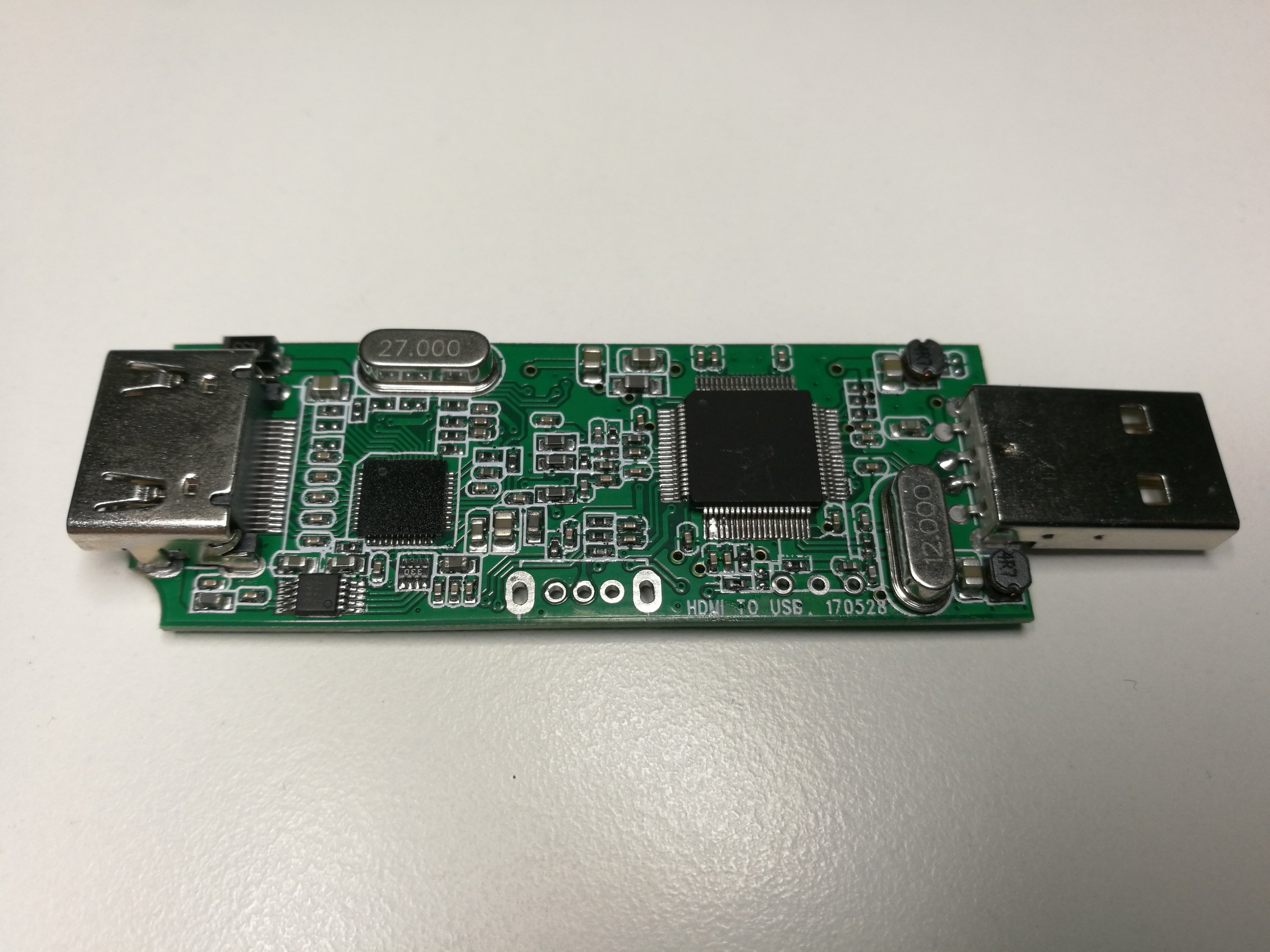

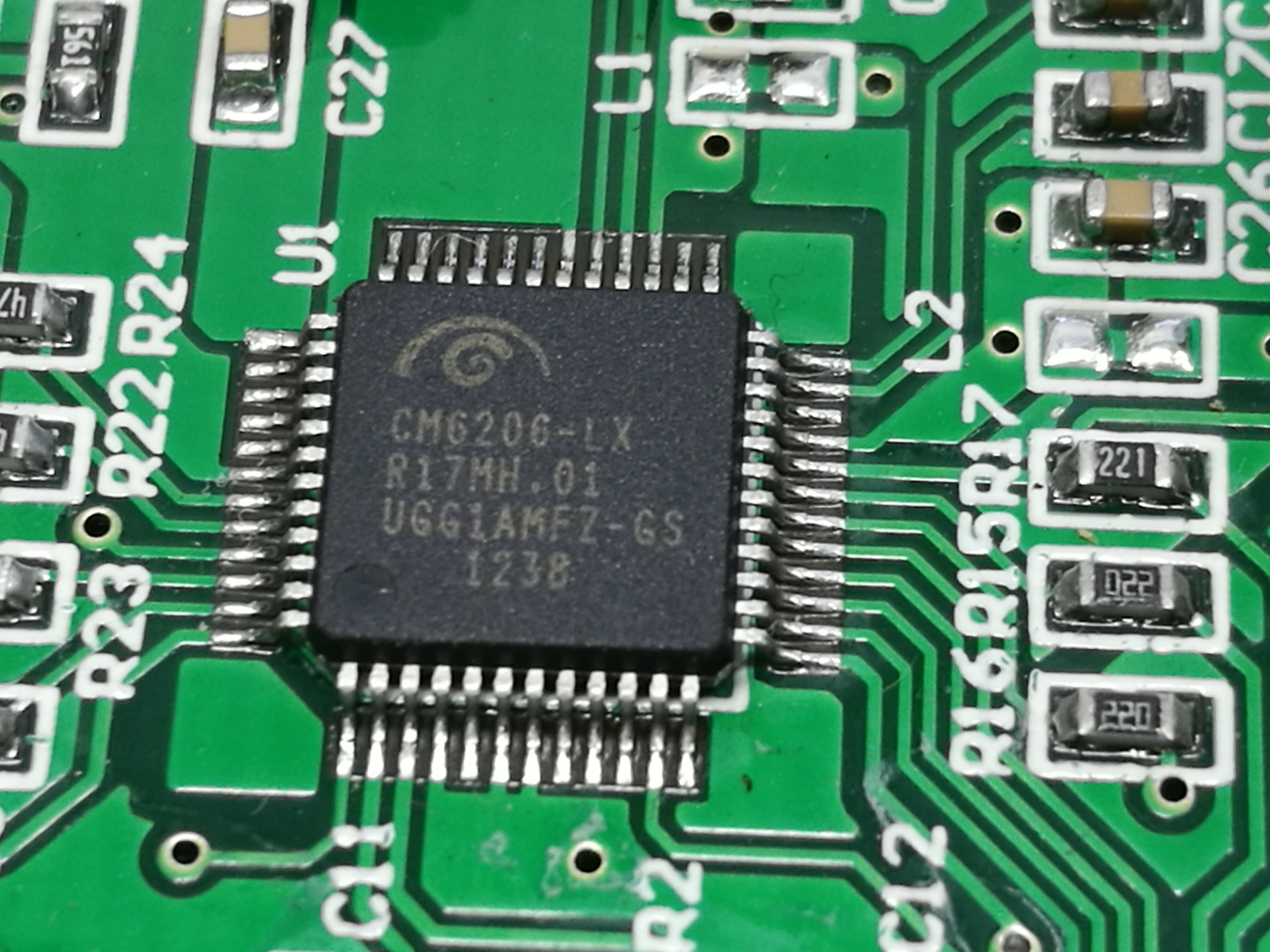
Component markings on chip were sanded out on chips. The ended my first first step. The device was for some weeks on my misc electronics trash bin waiting if it was of any use for some application (like could drivers be found for download that make it work or something else).
Later just for testing decided to test Mini Portable HD USB 2.0 Port HD 1080P 60fps Monitor Video Capture Card For PC device on my older computer where I had earlier used this analogue video to USB converter device.


I was amazed that Mini Portable HD USB 2.0 Port HD 1080P 60fps Monitor Video Capture Card For PC device was recognized EasyCAP analogue video to USB converter. Why would this device look like analogue video interface when the video coming from HDMI connector is digital video signal. Weird.
I got video on same resolutions and quality as I did with analogue digitizer – not at 1080i HD quality I fed to HDMI input. The recorded video even seemed to have same type of noise and interference on the signal as analogue composite video signal has. Clearly this device was will not record in HD quality. Even if I tried adjusting settings, I could not get anything close to HD quality recording from this (capture maxes out at 720×576). So I consider it as bad HD capture card (at least without the original drivers if they are in any way better).
Based on the results I start to suspect that this device could internally somehow convert first the signal to analogue composhite video that is fed to analogue video to a cheap USB converter. Then some Google searches started to reveal that my what I suspect could be right:
1080p 60 FPS HDMI capture card for only $15? | UTV 007 HDMI USB Review concludes that some things ARE too good to be true. The capture maxes out at 720×576, interlaced 25 FPS, wrong aspect ratio, overscan crops out parts of capture, digital-analog-digital conversion means poor quality.
Mini Portable HD USB 2.0 Port HDMI 1080P 60fps How to install and capture using VirtualDub review video says that while the image quality might not be best, but it is only $15.00. The mentioned problems are limited resolution, it makes picture interlaced and flashes sometimes. Can be used with 720p or 1080p source when all you need is lower resolution video. Recommendation is to give a little more money and get uncompromising quality with capture devices around $100.
HD Capture – USB 2.0 HDMI capture card REVIEW & TEARDOWN video investigation reveals the dirty details I was suspecting that indeed this device seem to be converting first HDMI to analogue video and then fed the video signal to UTV 007 analoge video to USB chip. This reviewer thinks on video description “This thing should not exist”.

So it seems that using) Mini Portable HD USB 2.0 Port HD 1080P 60fps Monitor Video Capture Card For PC device is approximately same in quality than using cheap analogue video to USB converter connected to HDMI to composite video downscaler. The result is quite poor SD resolution analogue TV video signal quality video. If you want to produce 640×480 or so resolution low quality video stream as cheaply as possible, then this might be an option. If you want any decent HD quality results, then it is maybe a better idea spend more of your money on some better HDMI to USB converter or capture card (whatever that might be).


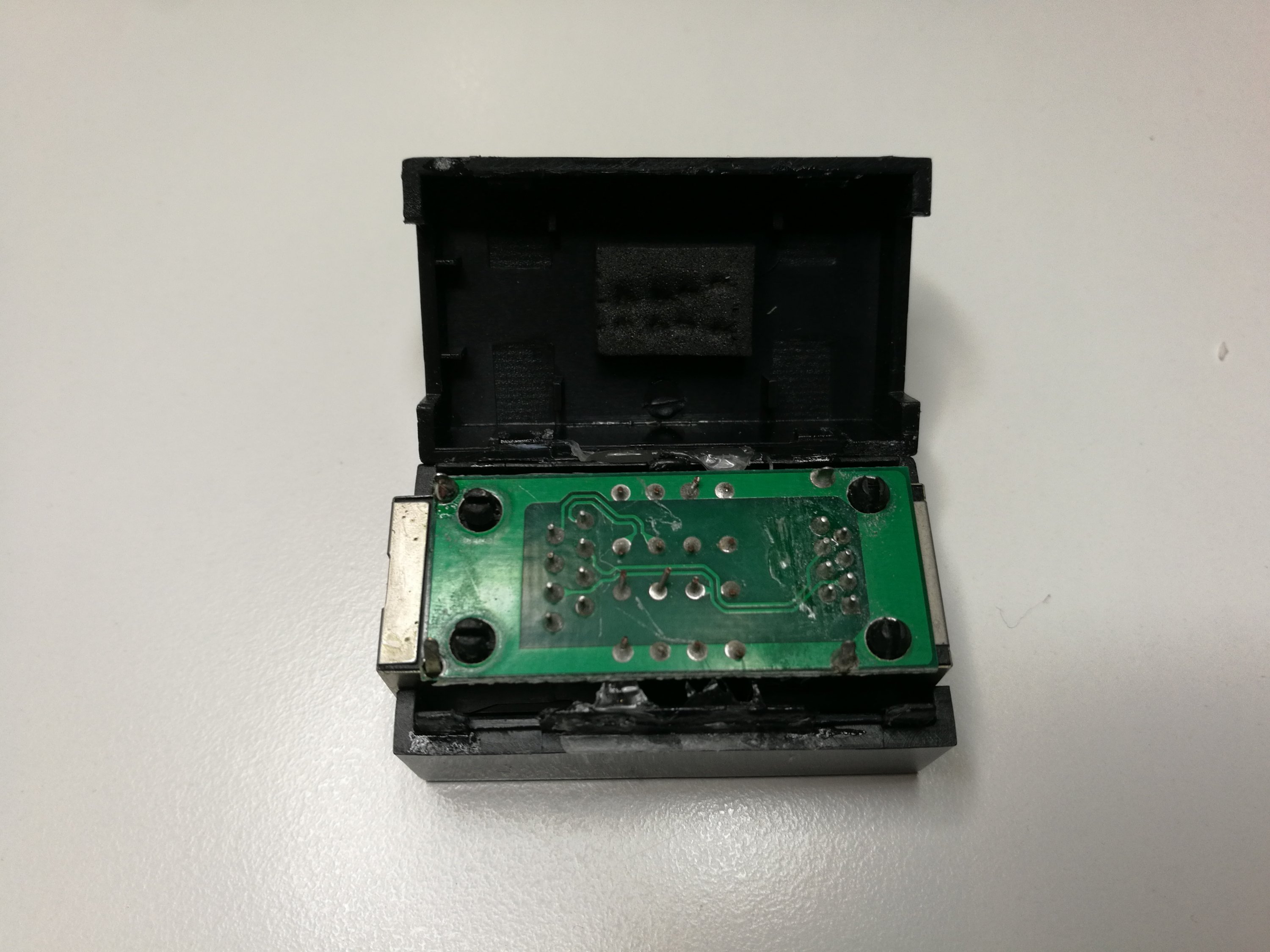


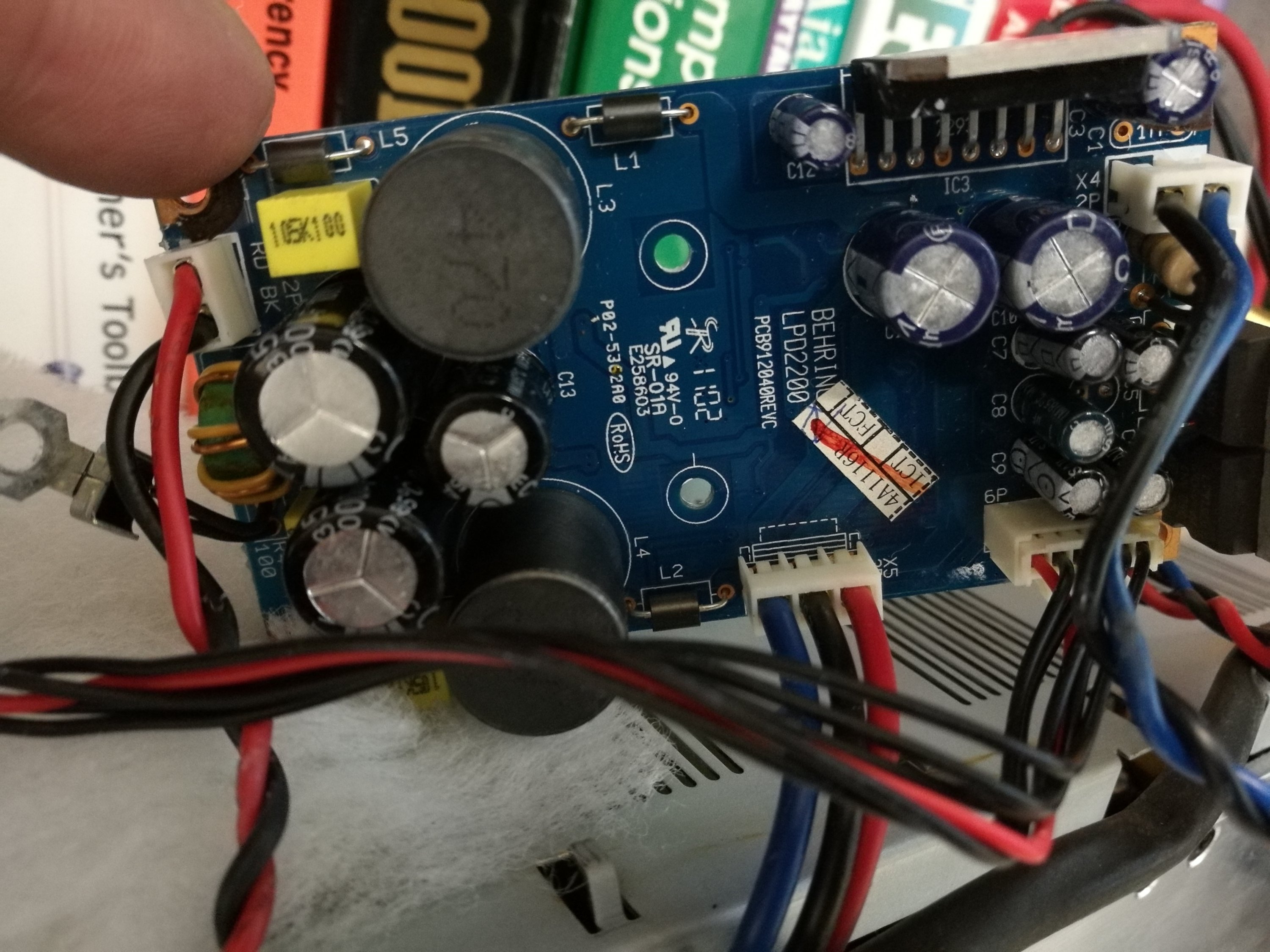
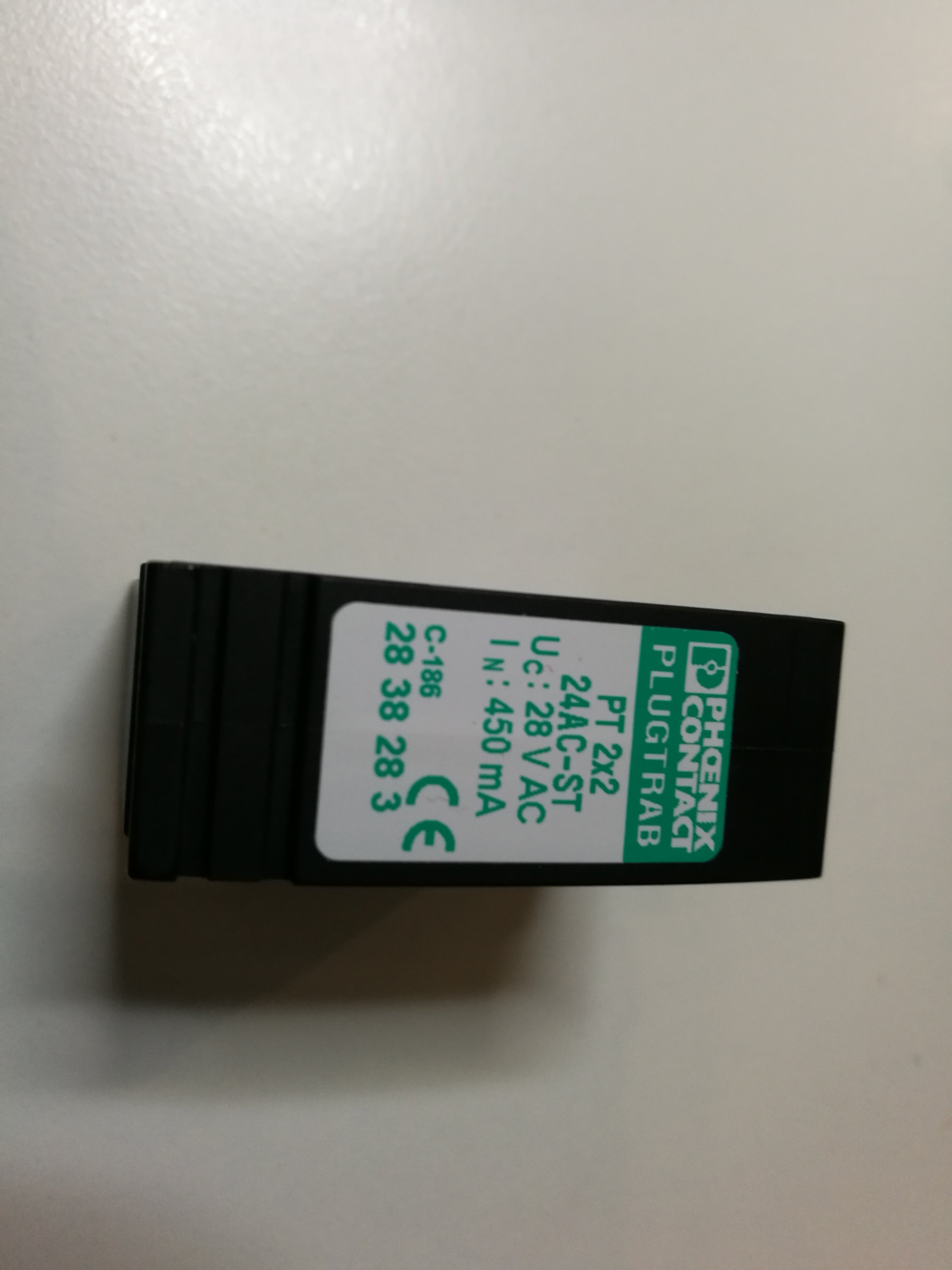
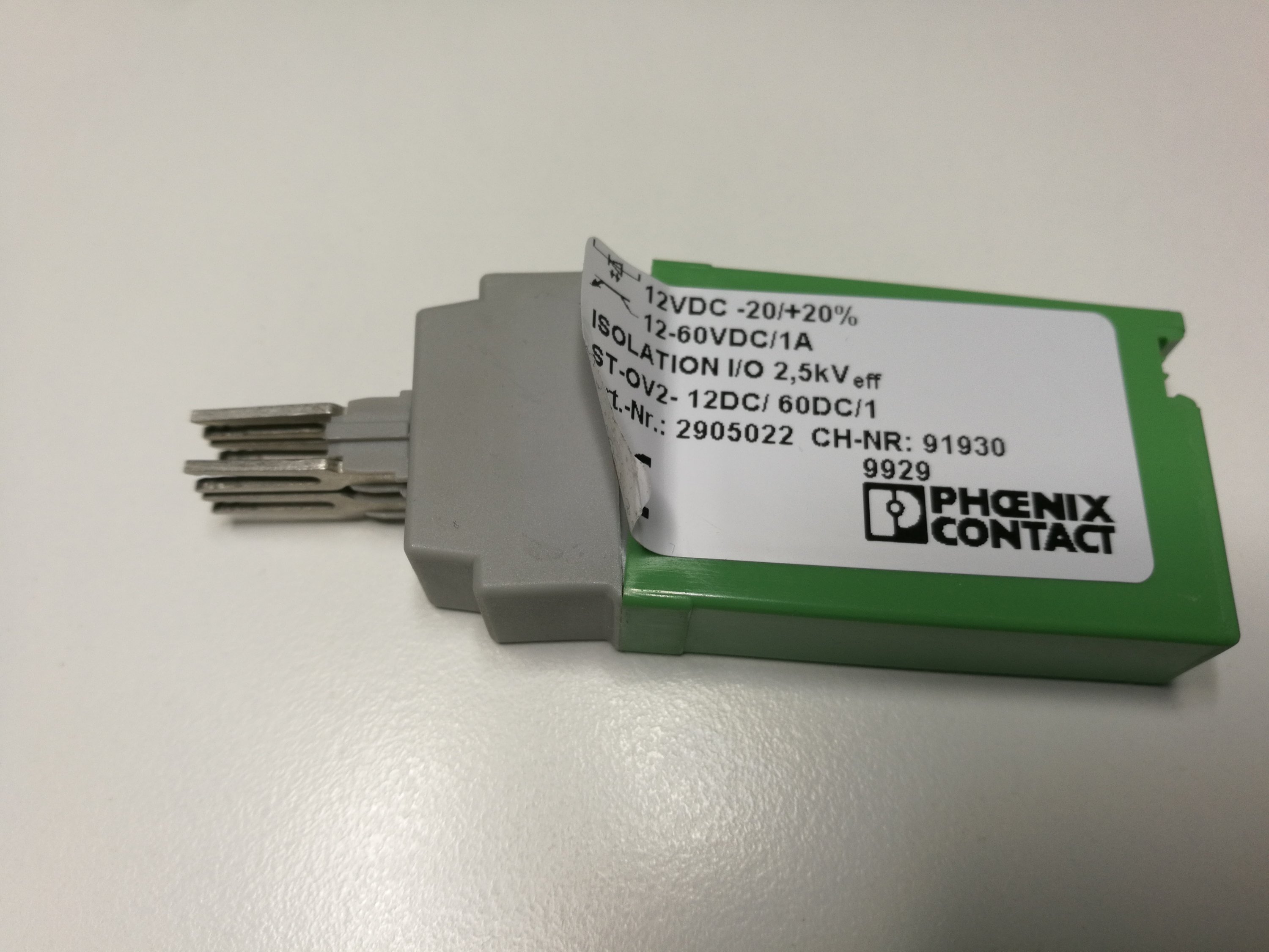
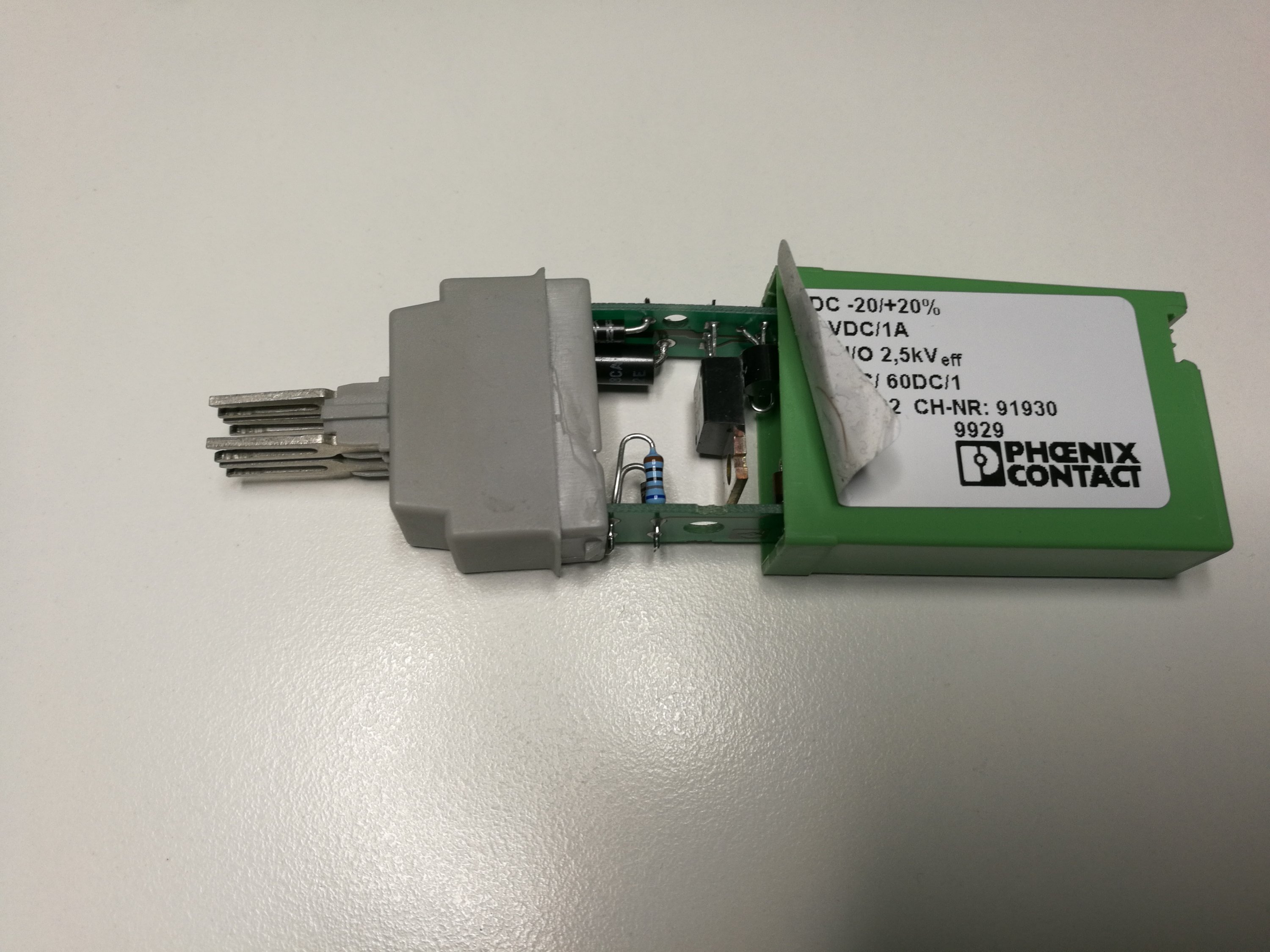
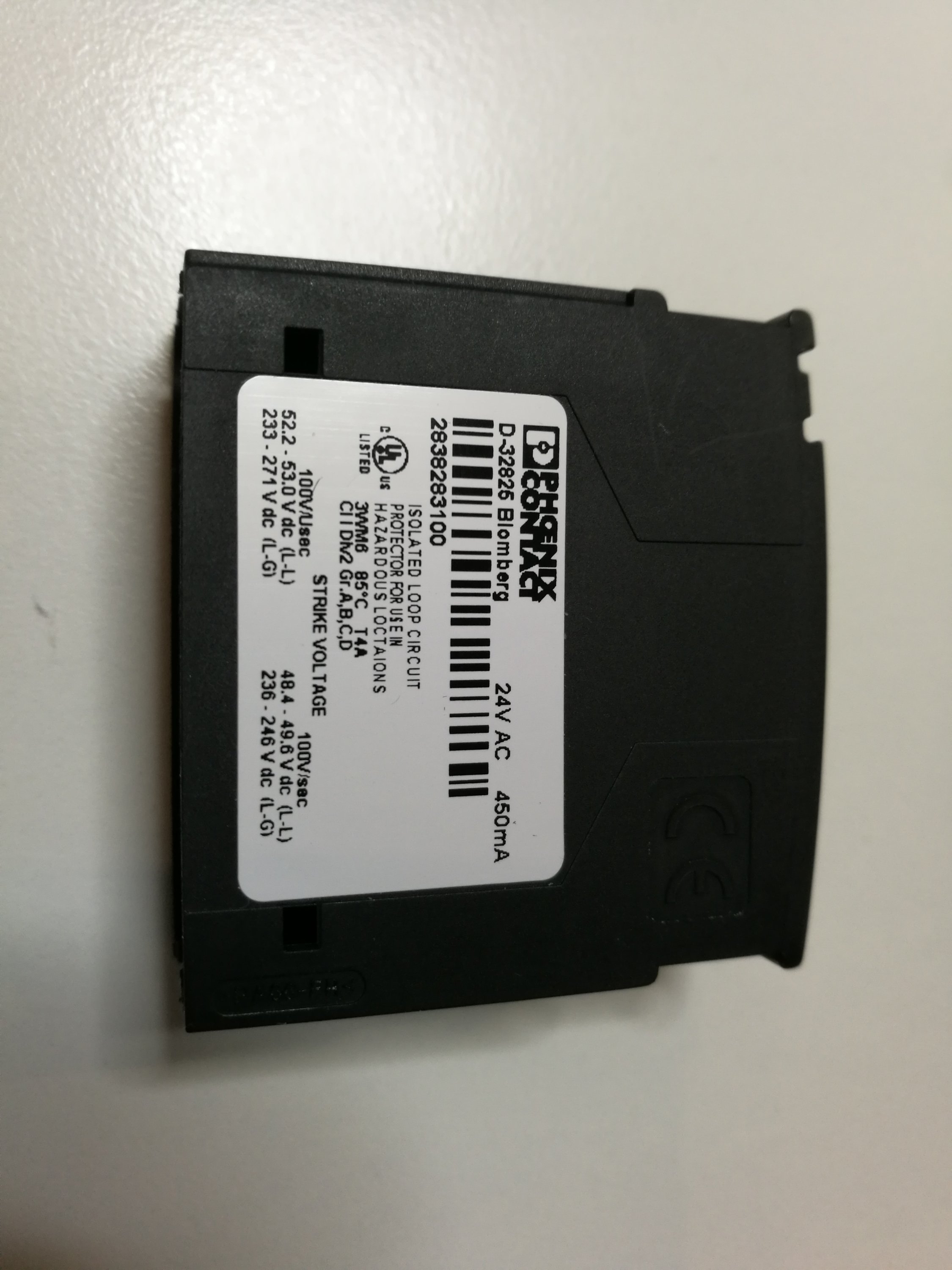 What is inside
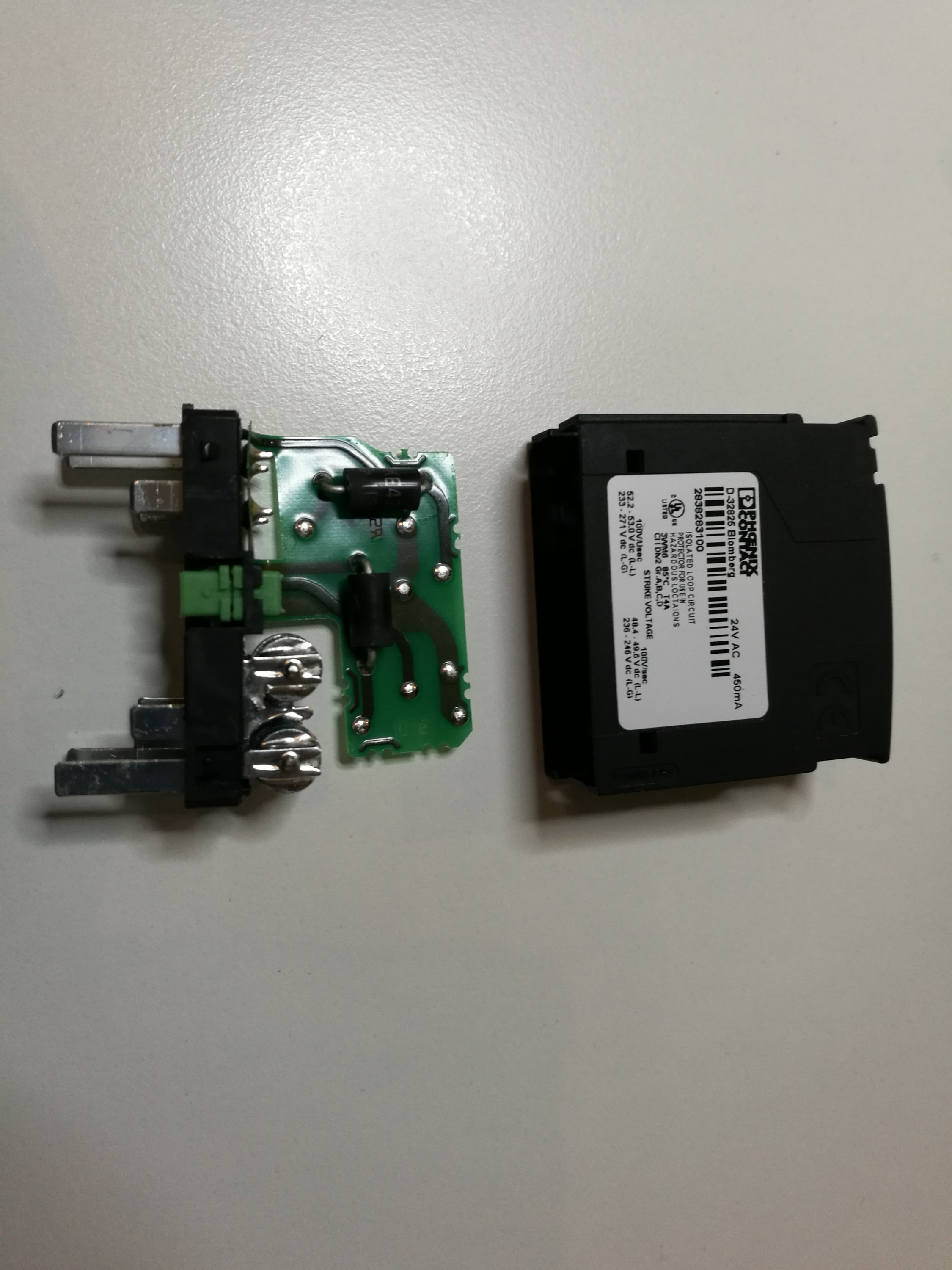
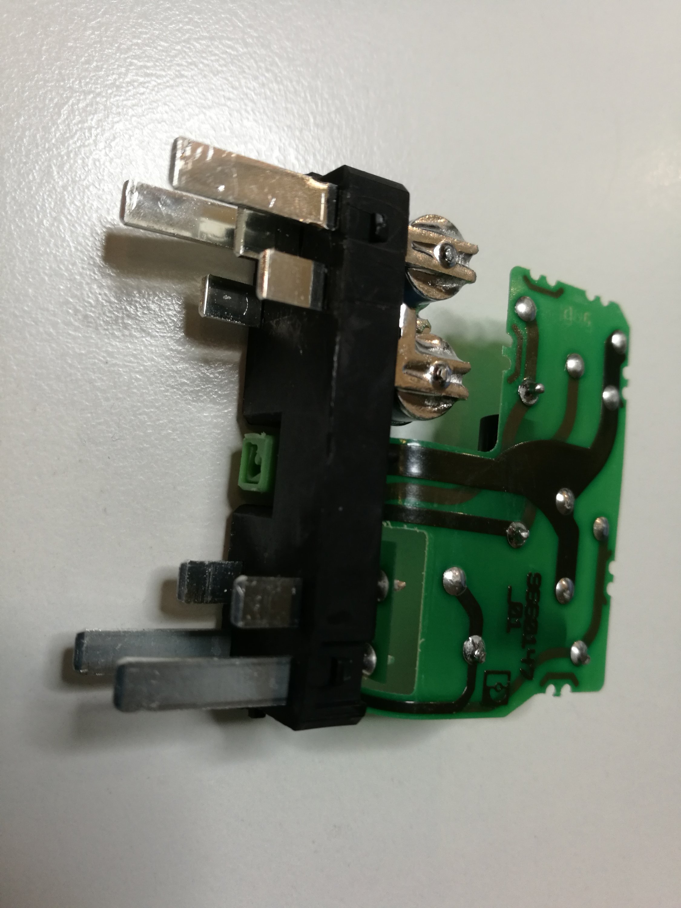
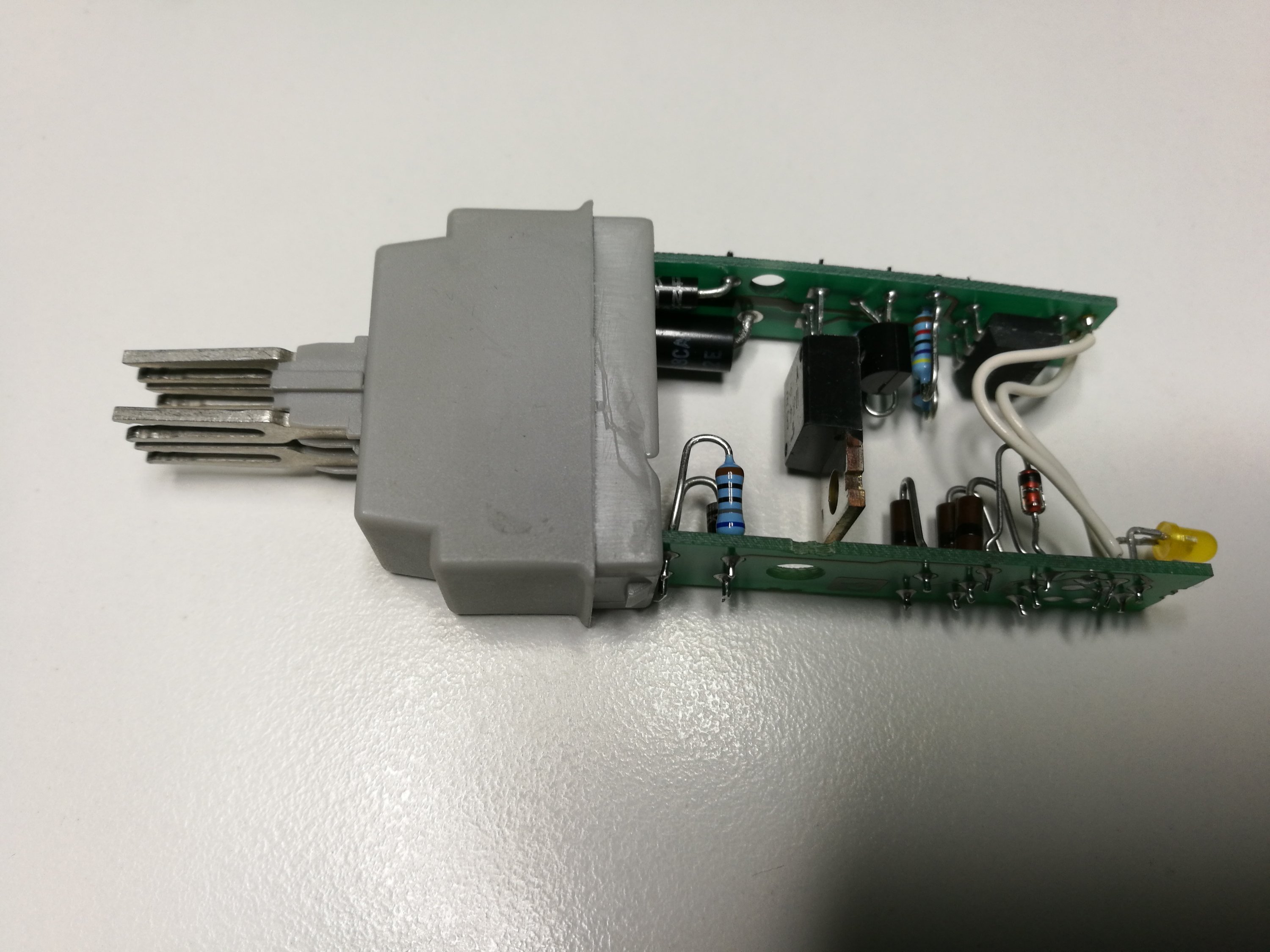
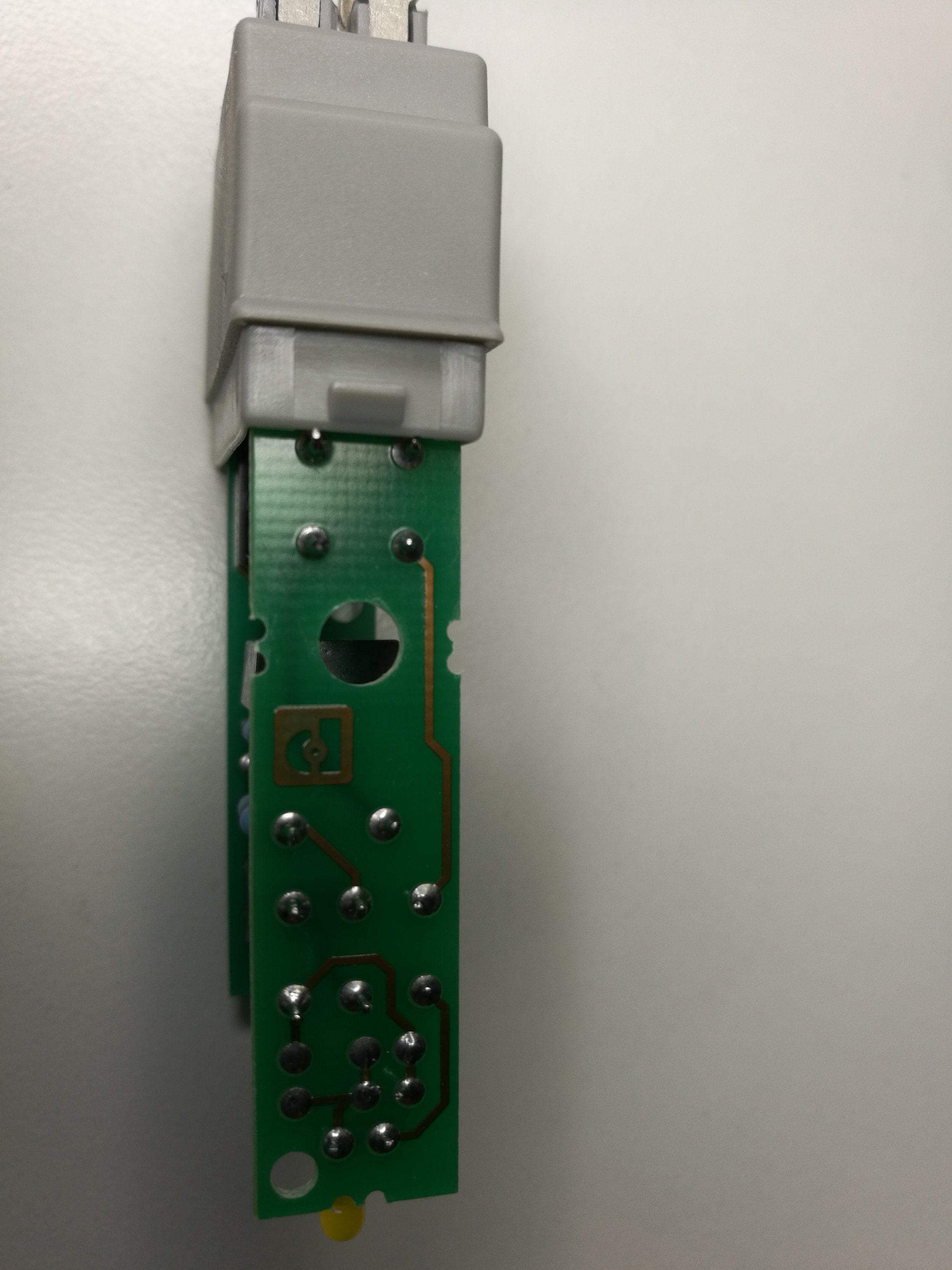
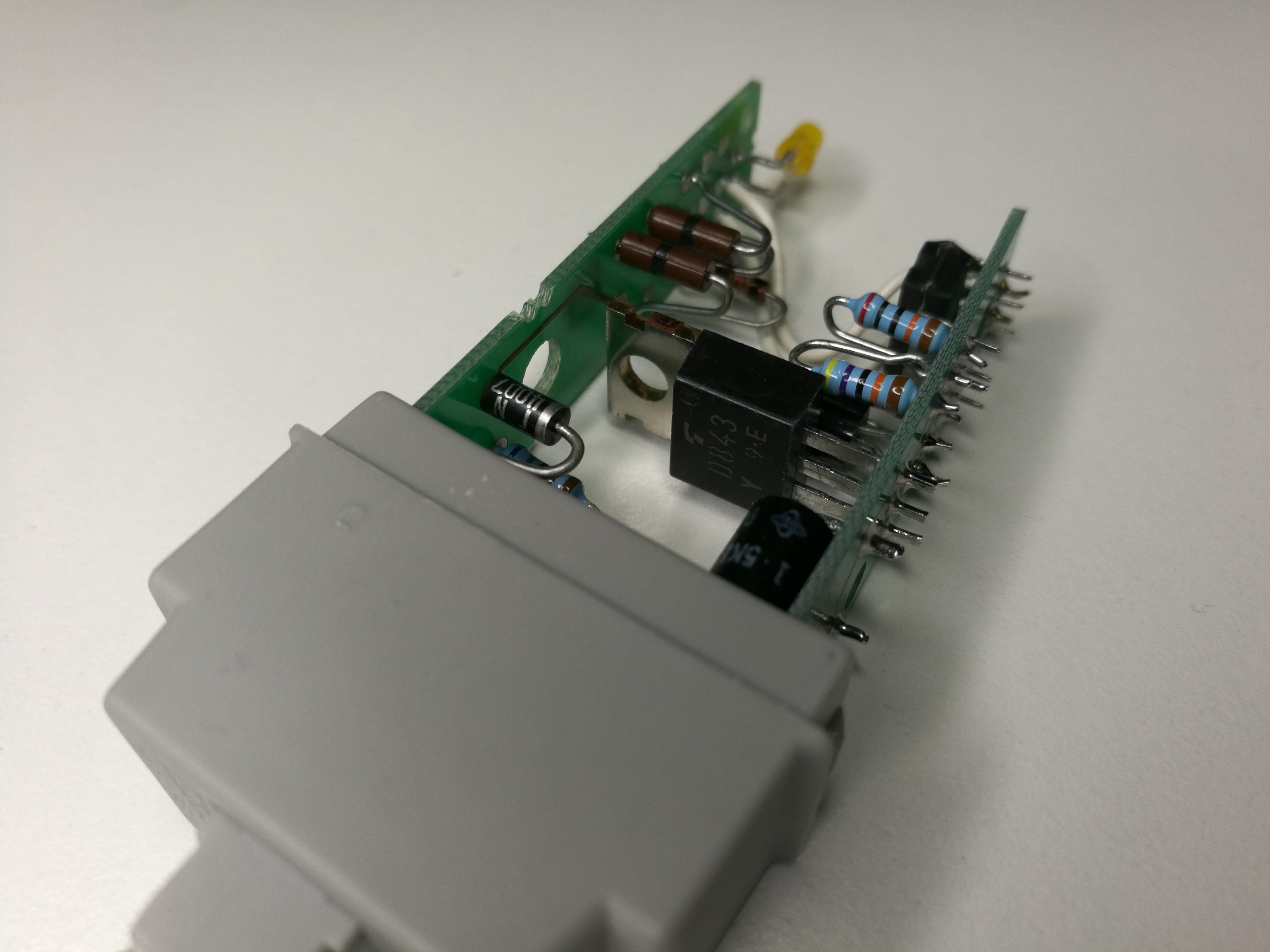
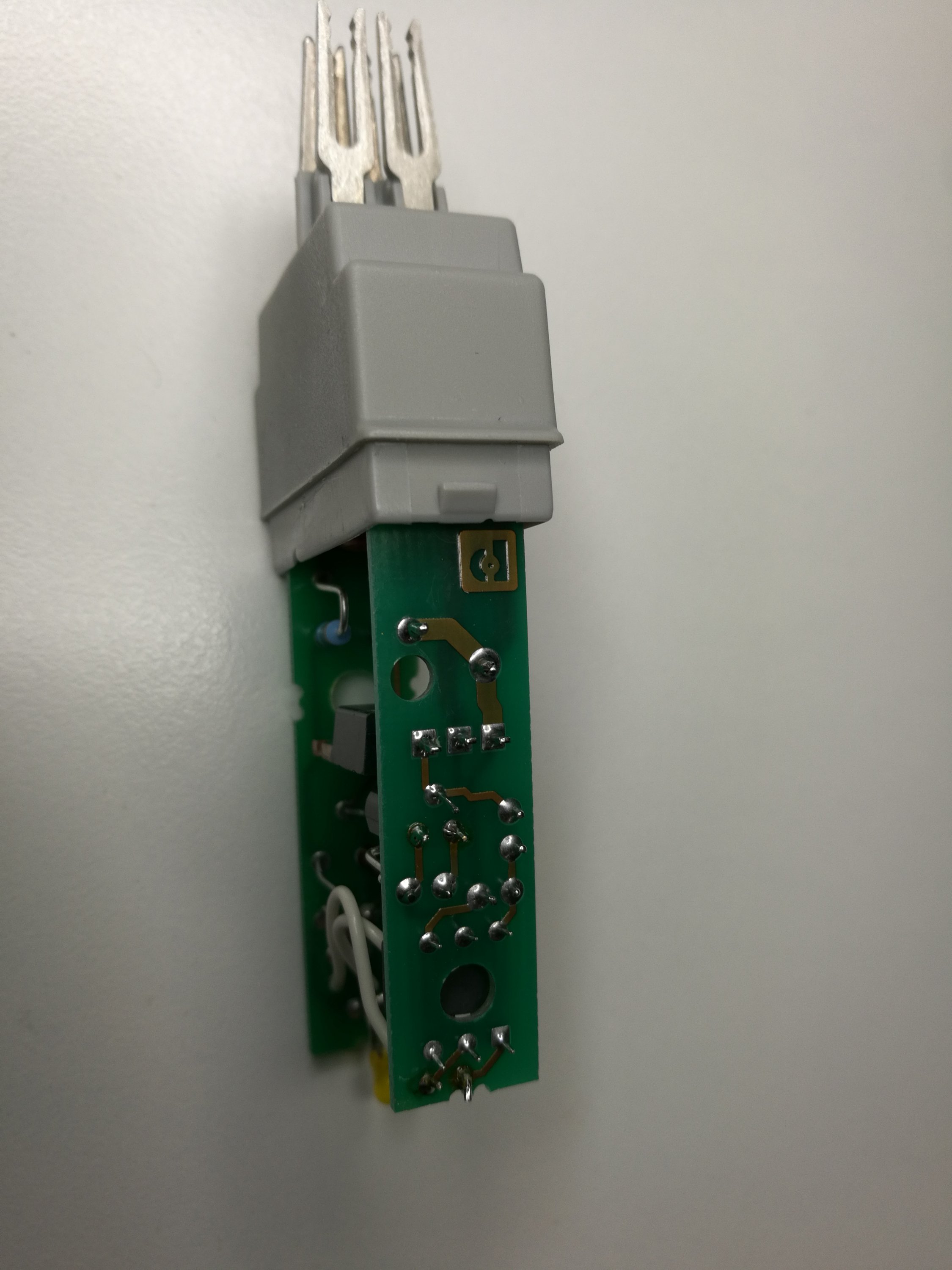
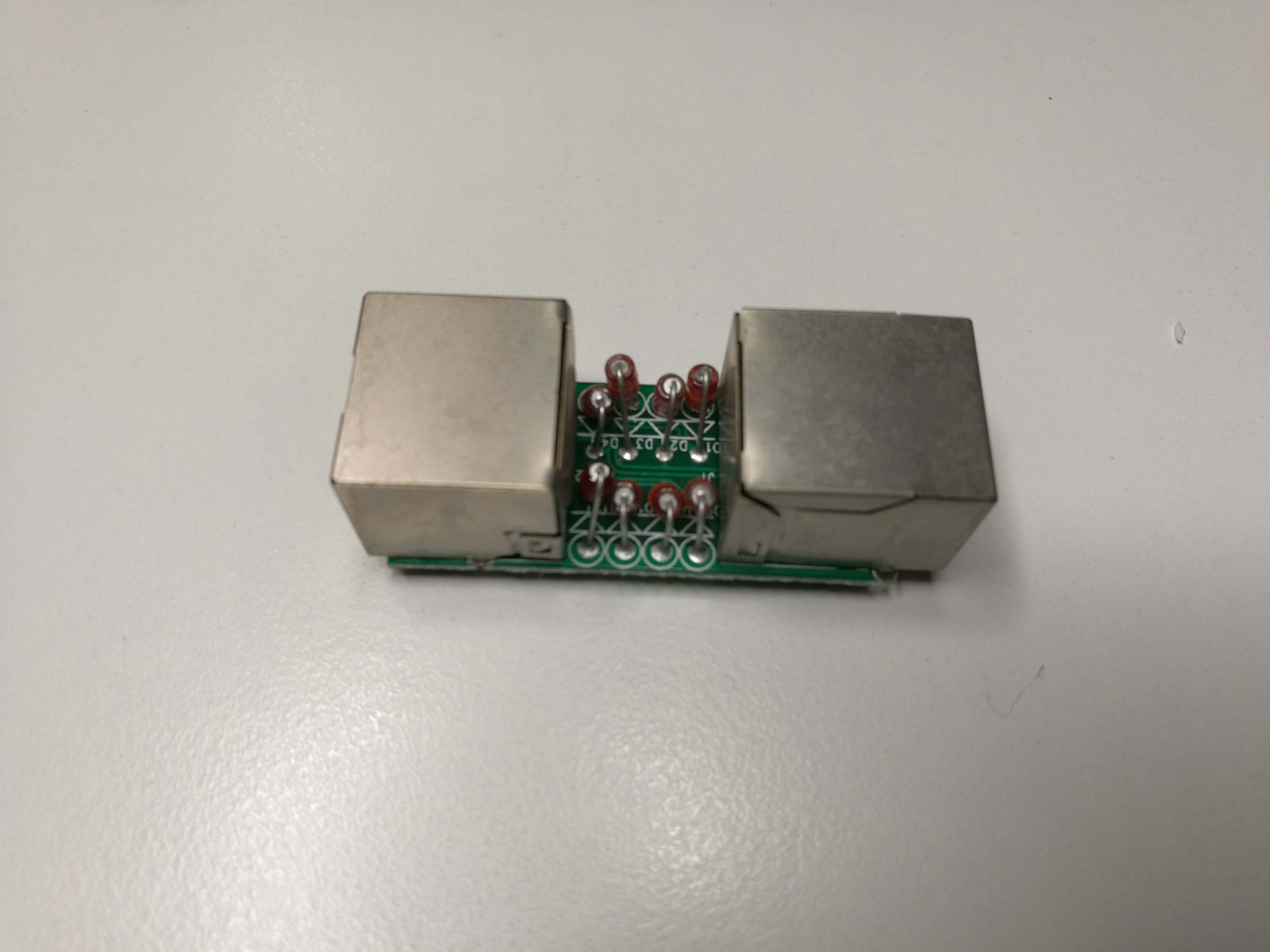
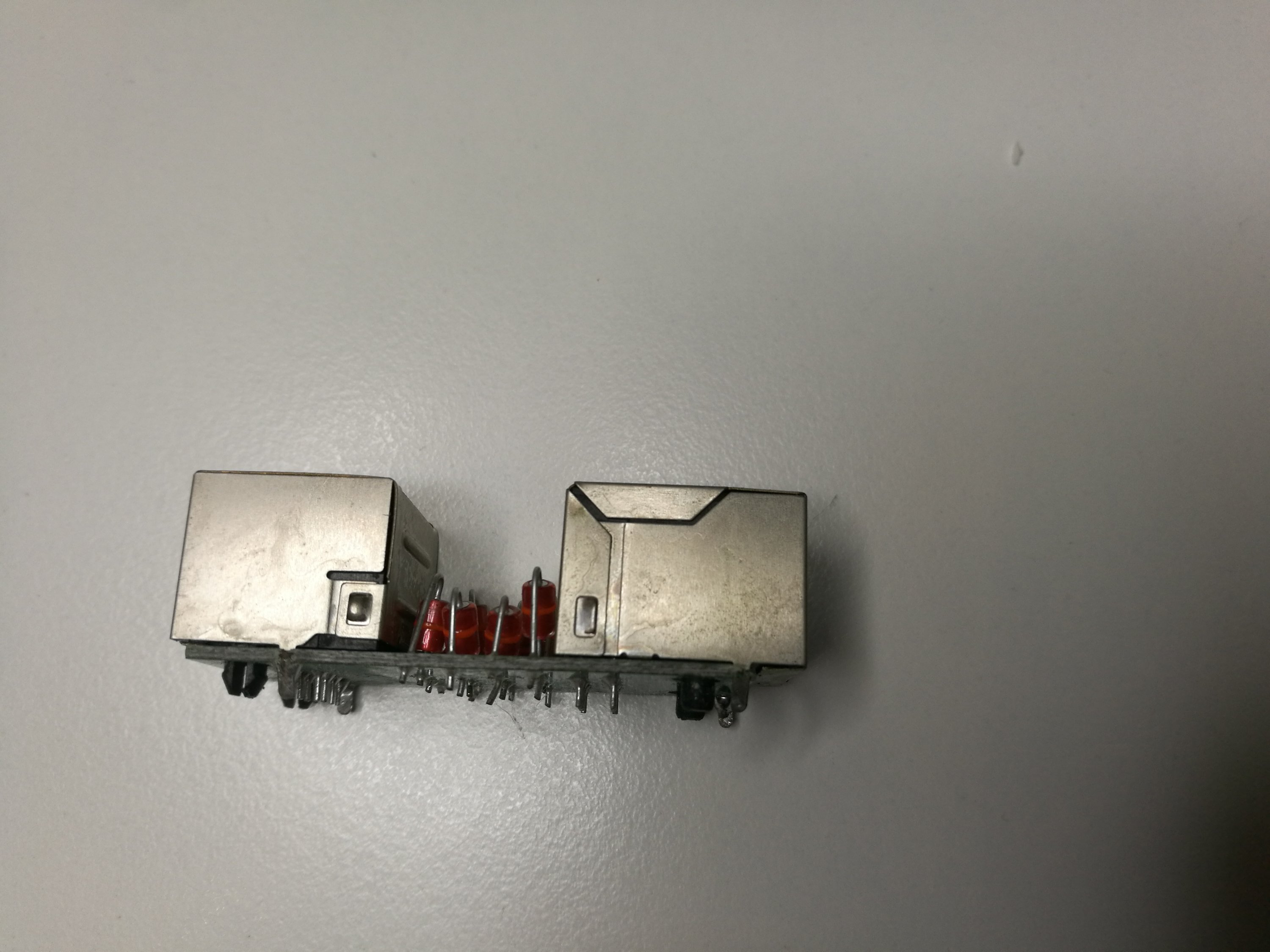
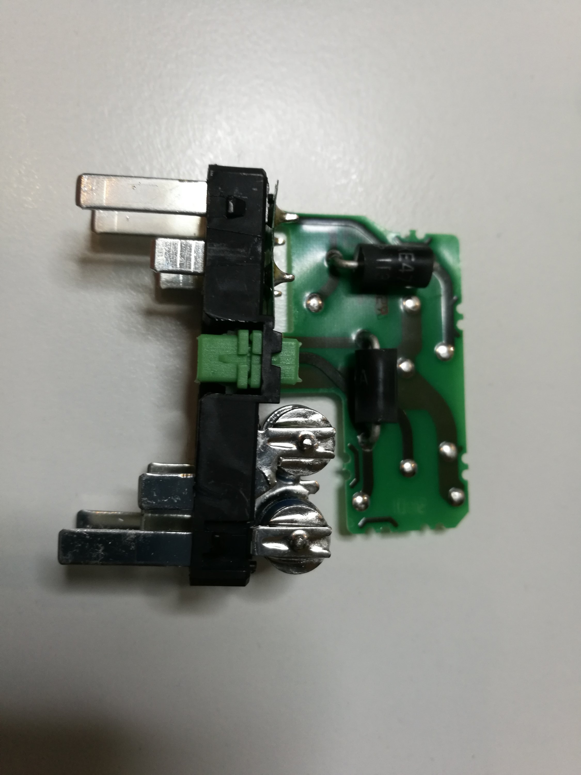 Components close-up
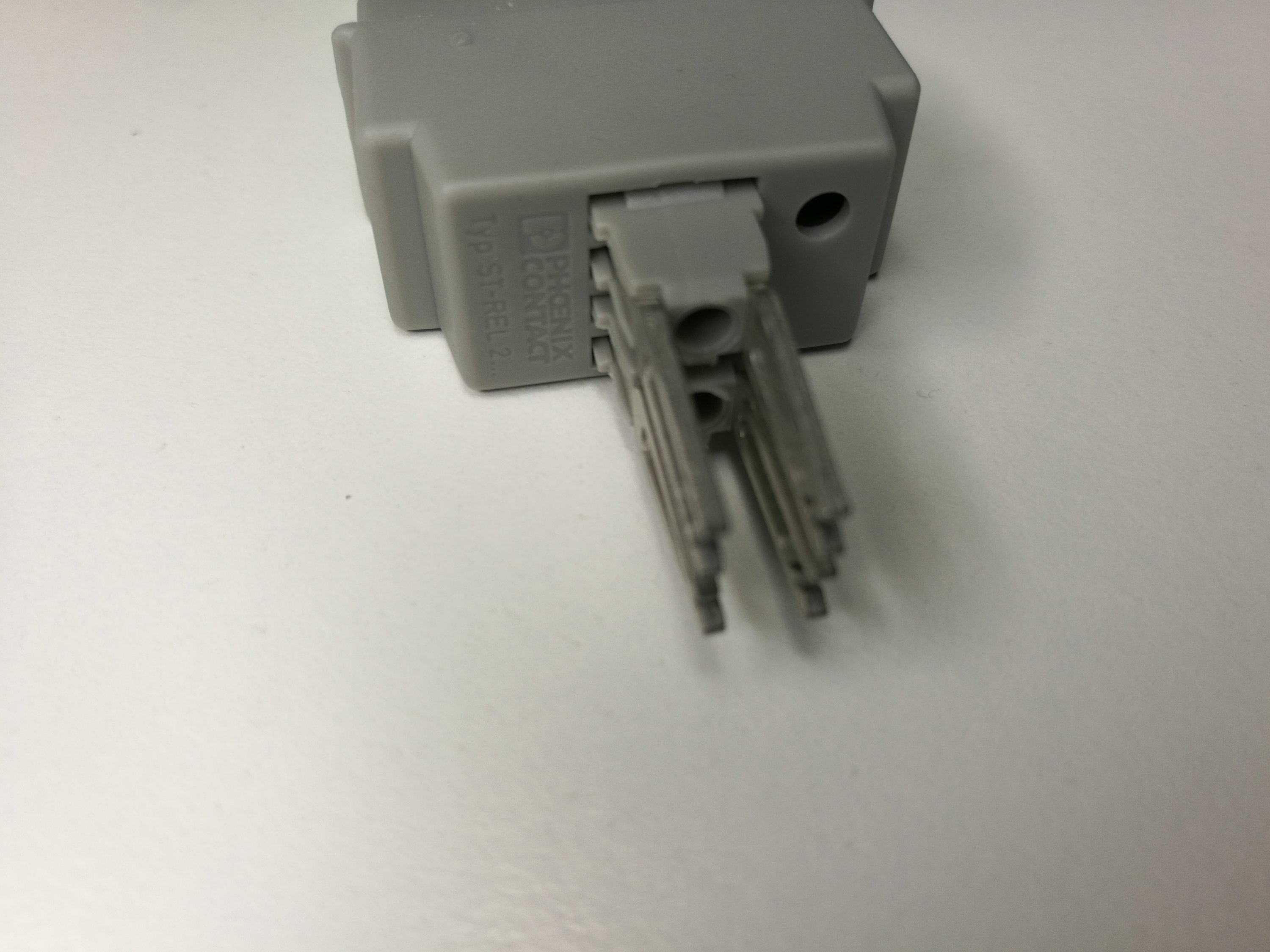
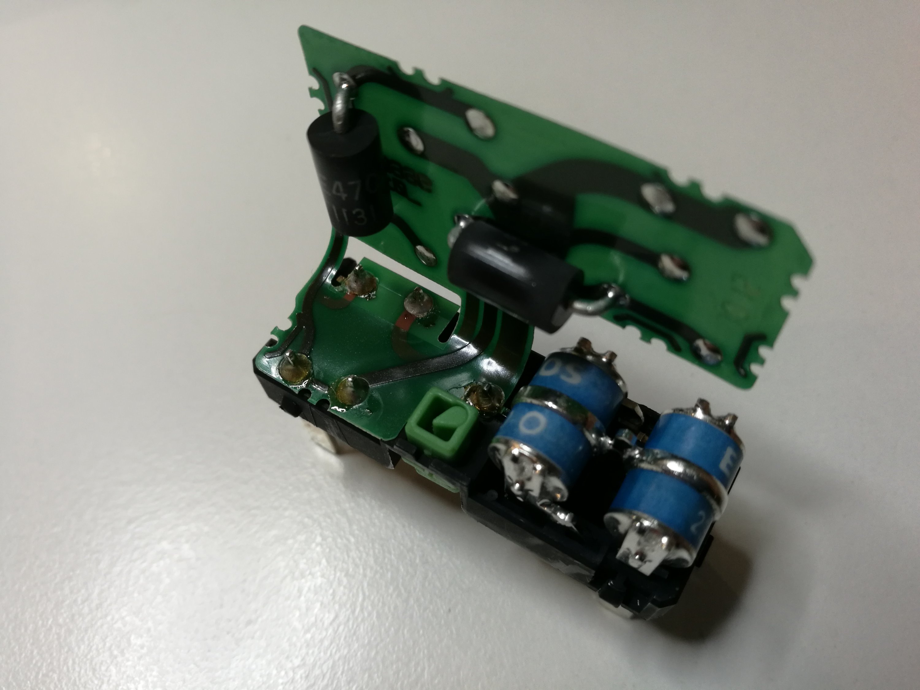 What was found was two dual gas discharge tubes ant two other over voltage protectors. The gas discharge tubes were connected to pins at one end (two protectors for two signal wire pairs).The contacts on other and go to flexible circuit board that has just those surgectors/zeners in it. Look like a bit of complicated electro-mechanical construction because it looks like just directly soldering the components to pins on bottom had done the same.