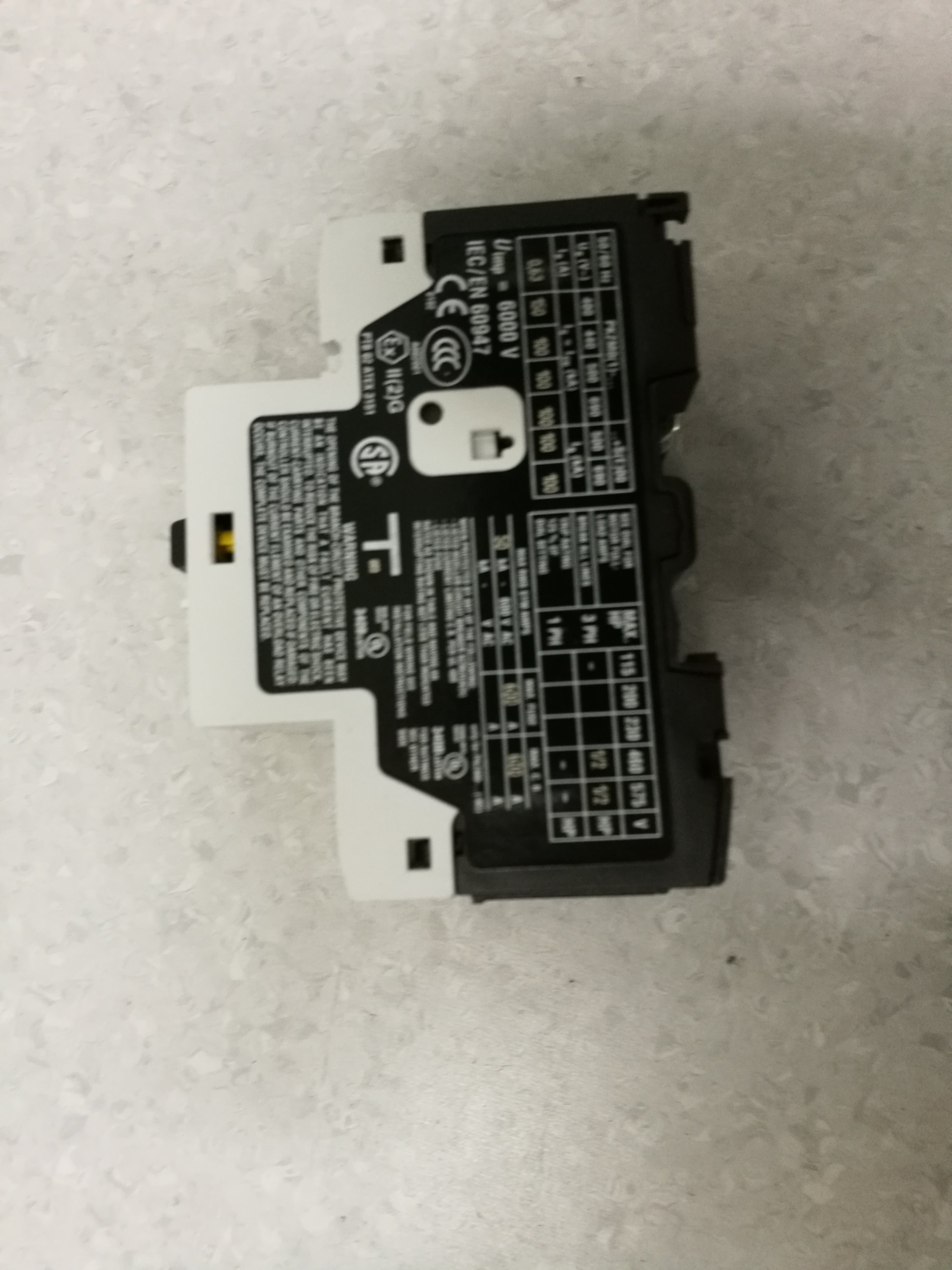
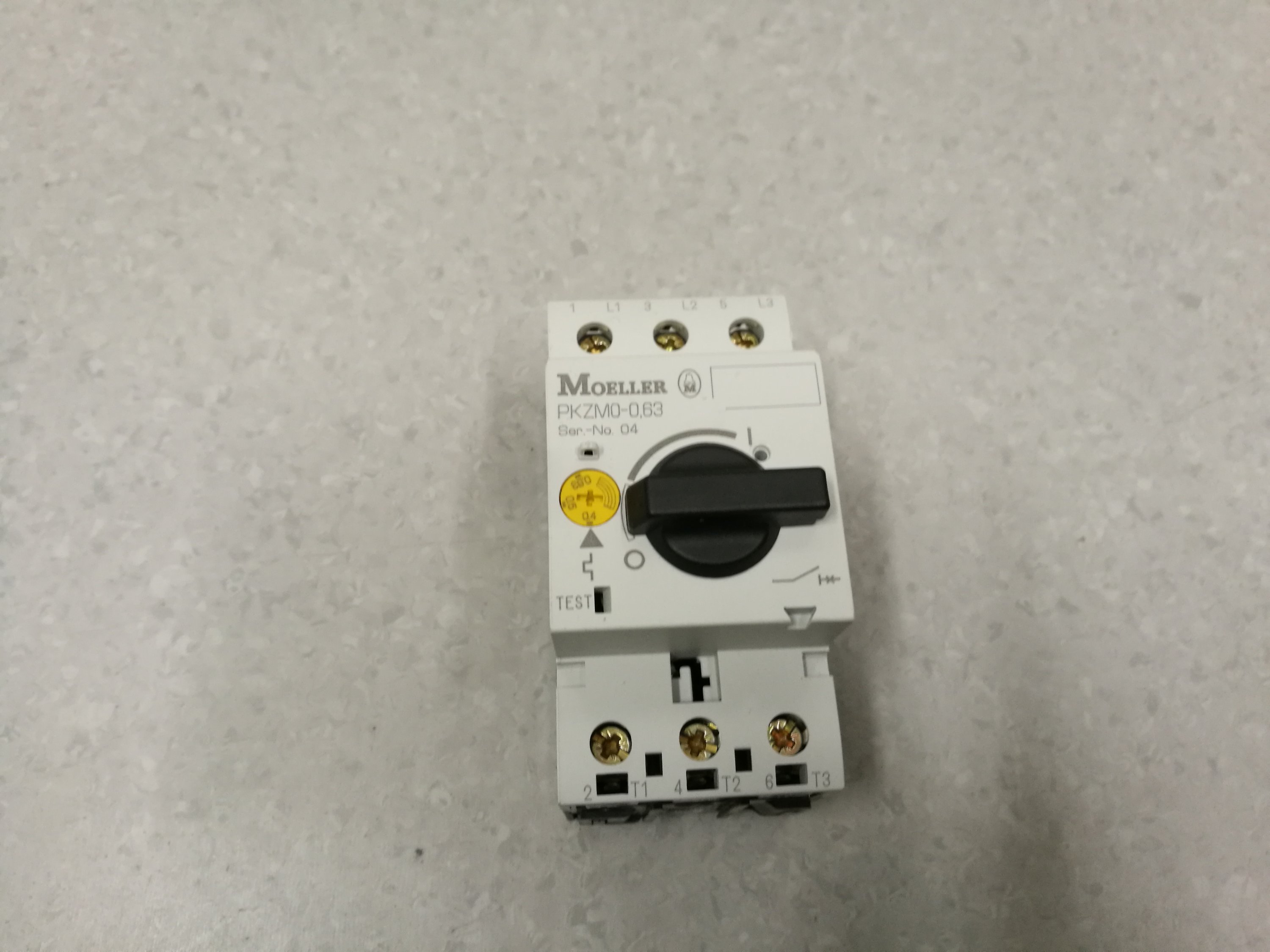
Here is GE MT03M motor protector: Contactor, Miniature, Overload Relay, 5.5-8.0A Range
• Control circuit up to 690V
• Power circuit up to 690V
• Three-pole differential (phase unbalance protection)
• Automatic ambient temperature compensation between – 25ºC and + 60ºC
• Choice of manual or automatic reset
• Direct connection to contactor or independent mounting using accessories.
• Screw and Ring terminal versions
• Terminals protected against accidental contact in accordance with VDE 0106 T.100 and VBG4.
• Terminal numbering in accordance with EN 50005
• Degree of protection IP20 (EN 60529)
• Additional auxiliary contact block 1NO (with manual reset only)
This device is designed to be installed to a motor controlling contactor. It detects overload situation and then disconnects the coil control current from contactor which causes it to open the contacts – thus disconnecting motor from power source.
![]()
• Reset button, 2 positions : Manual(H) and Automatic(A) by turning the blue selector.
• Stop push button, independent of reset (red).
![]()
![]()
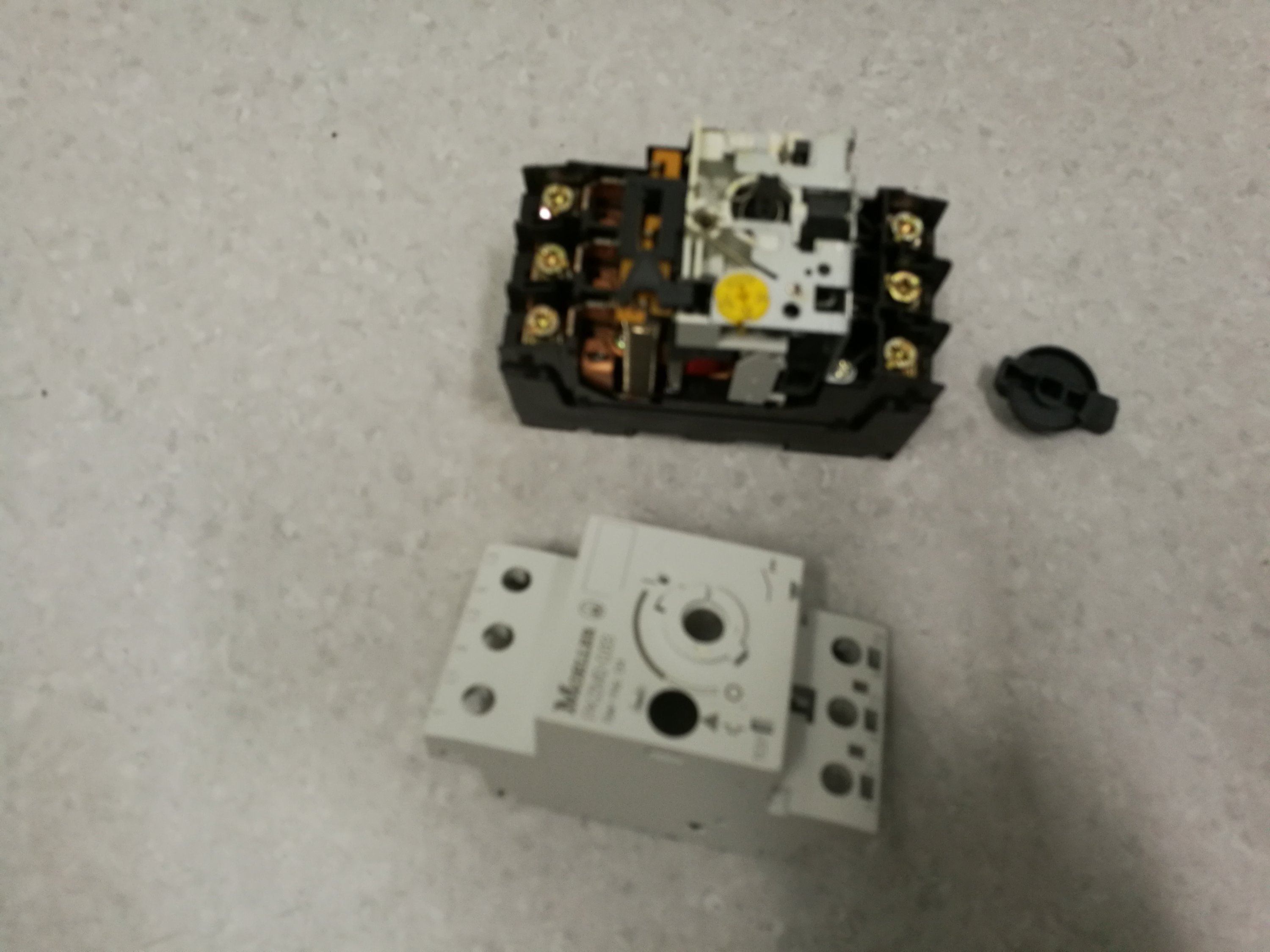
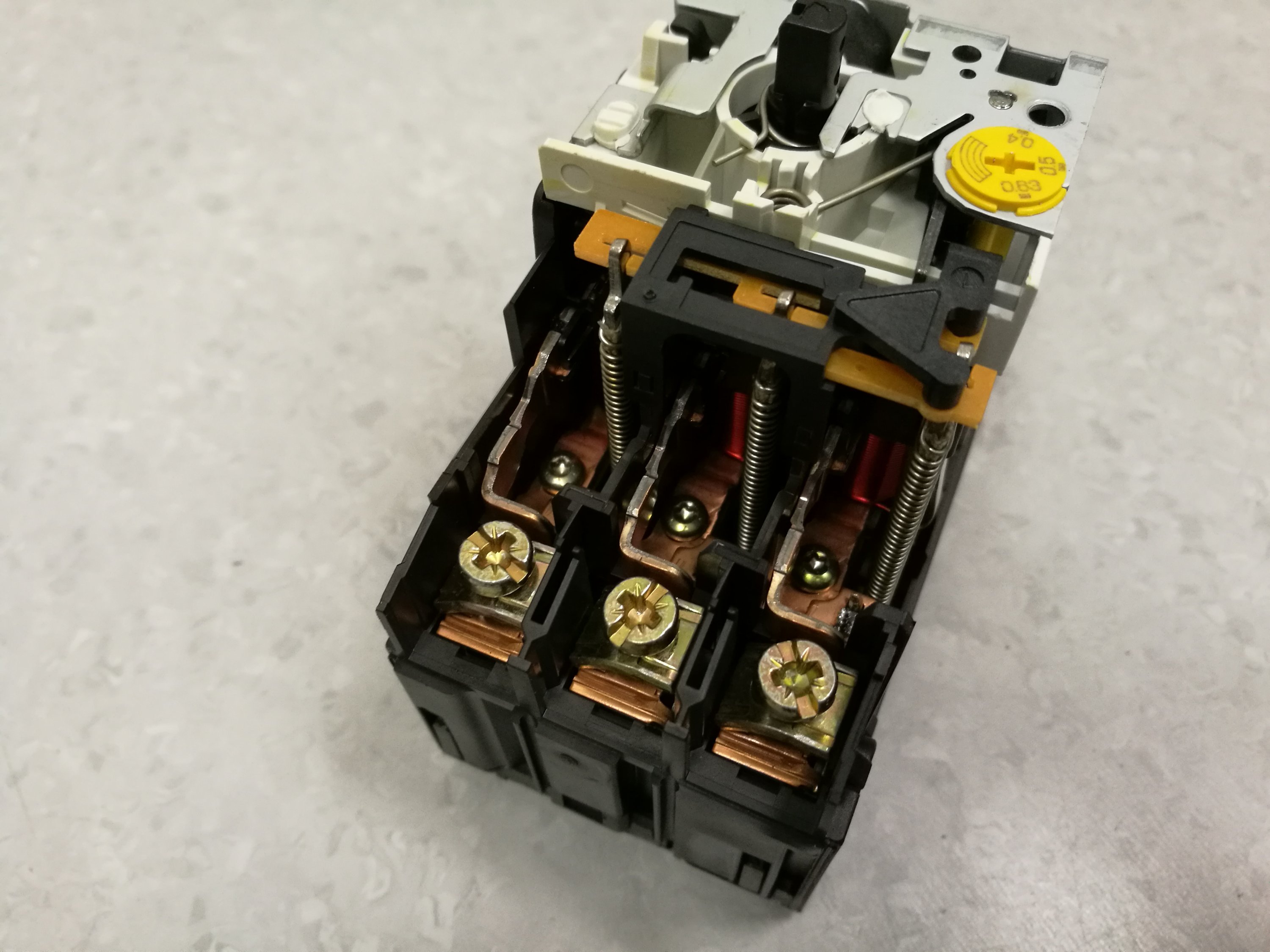
Look inside
![]()
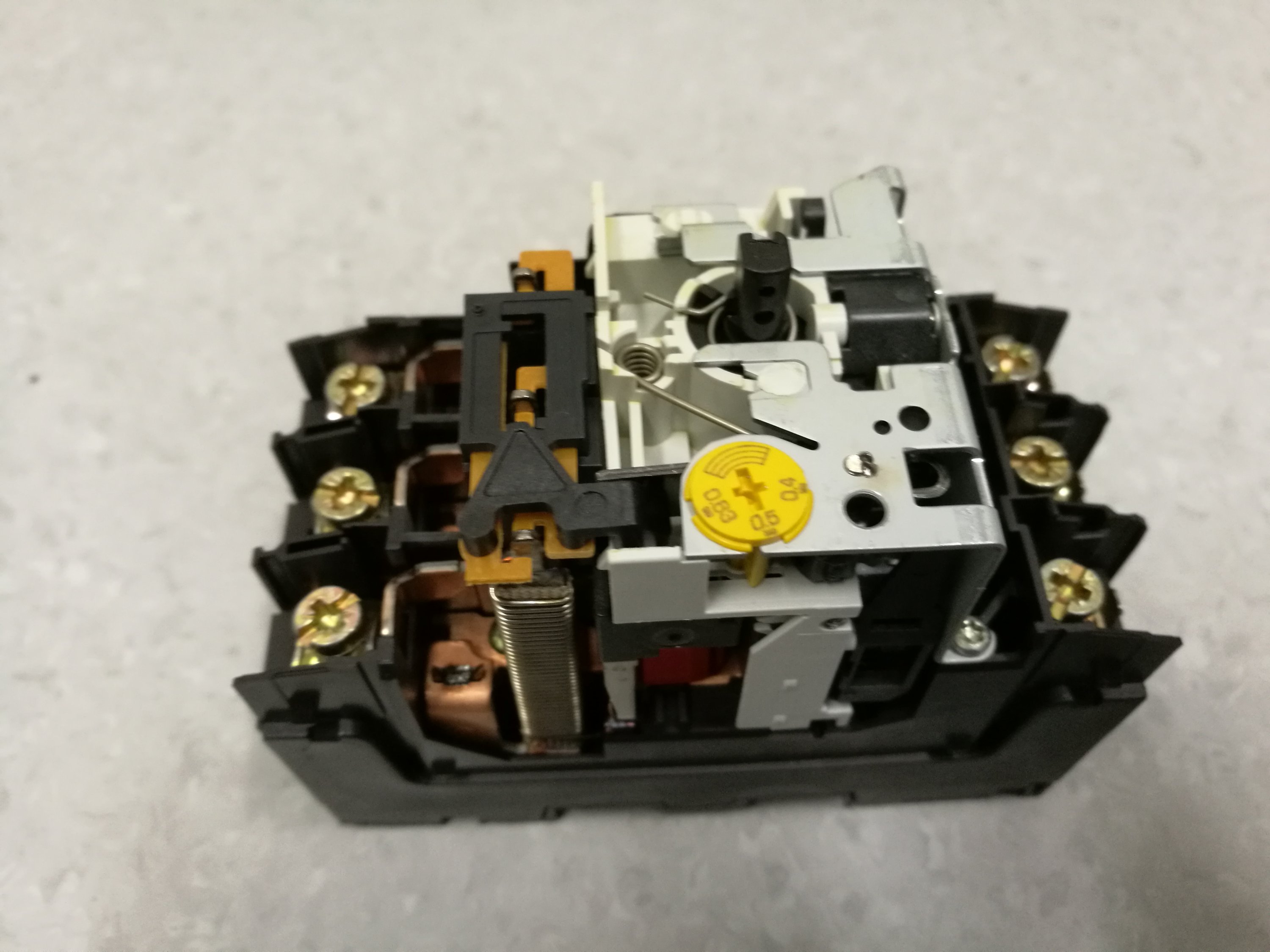
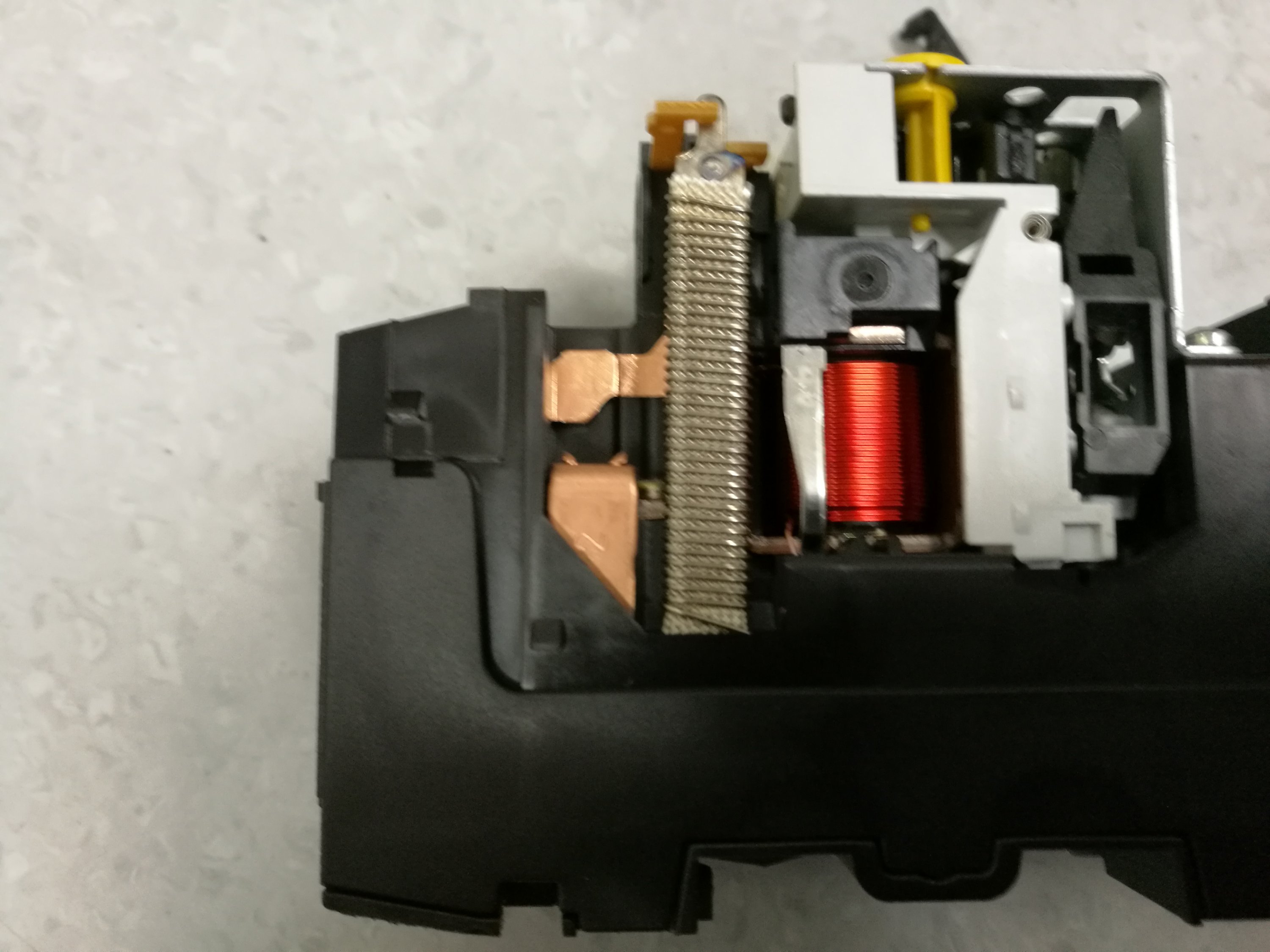
Closeup
![]()
There are three bi-metallic strips that have heating wires around them. When the temperature gets high enough those bend to trip the device.
The complicated looking mechanism connected to bimetallic current sensing parts is designed to work so that it when all three phases are loaded with same current, it trips at rated current. When there is serious imbalance (different currents on different phases), the device works at lower current rating.
There are no opening contacts for the phase currents, because the contactor handles breaking the current if needed. The only contact on this device is the one that breaks or makes the contactor coil drive current (on the left side of the device).
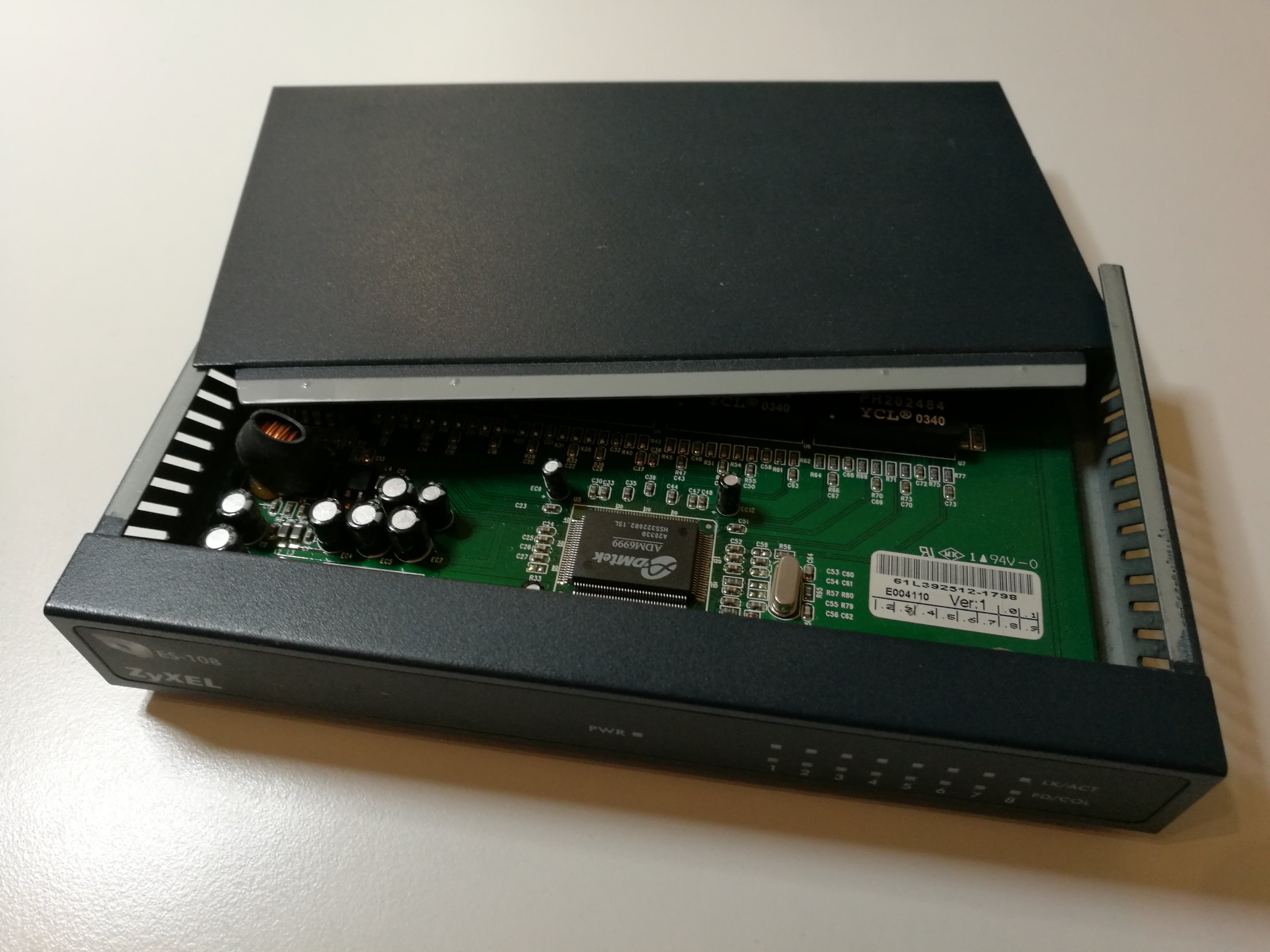
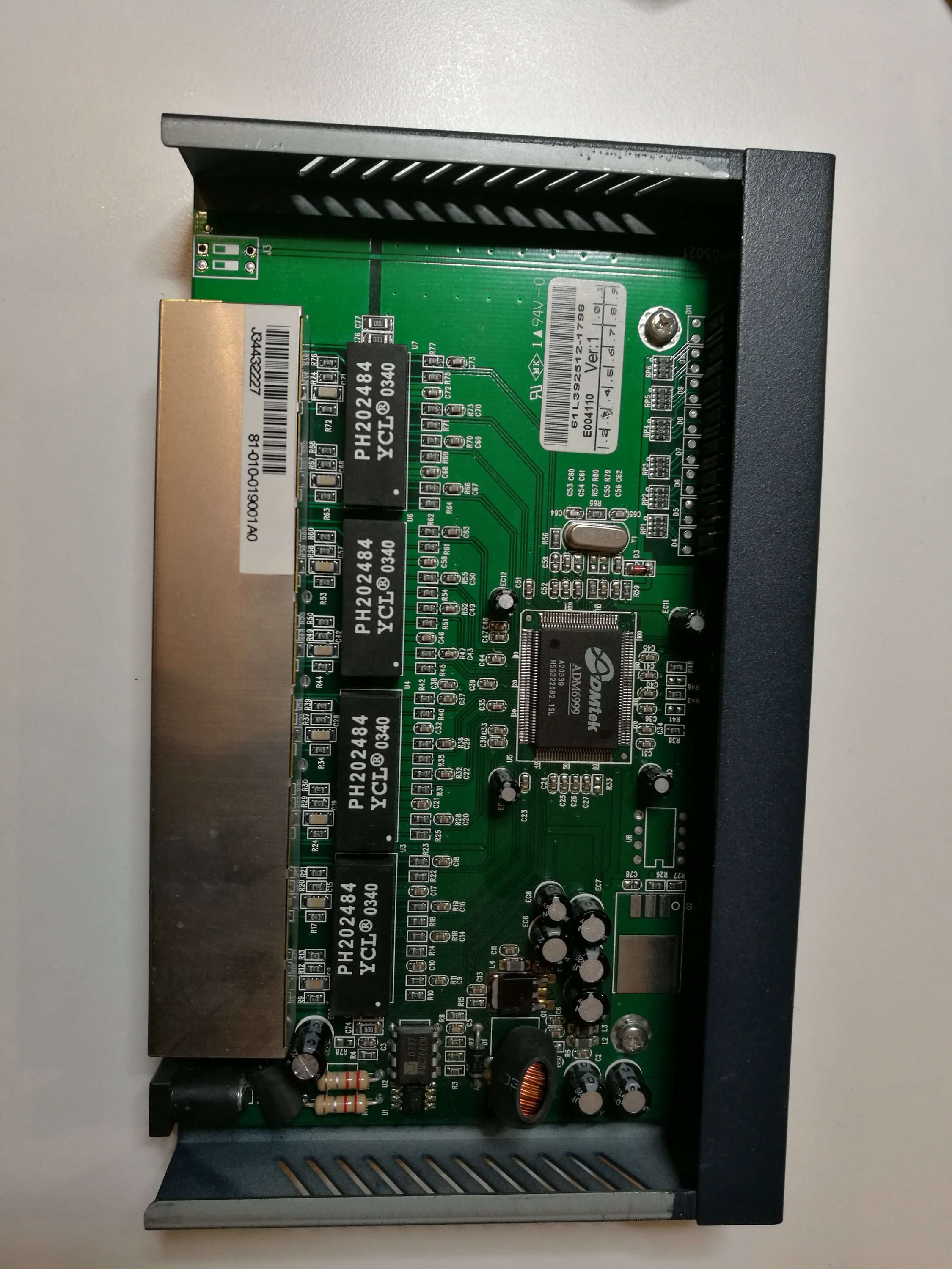
Check also my other motor protector teardown.